G&M Codes That You Need To Know When Developing CNC Post Processors
G0, G1, G2, G3 MOTION COMMANDS:
- The G0 command enables the machine to move at maximum speed. Rapid Motion.
- The G1 command enables controlled movement of the cutting tool in the direction of the feed rate provided to the machine. Cutting Motion.
- The G2/G3 command enables the machine to move in a circular or helical manner, either clockwise (CW) or counterclockwise (CCW), at the cutting position of the machine. Cutting Motion.
G4 COMMAND:
The G4 command allows the active program to be paused for the specified duration (P=milliseconds or X=seconds). G4 P__. (Program is paused for the specified duration in milliseconds (P)) G4 X__. (Program is paused for the specified duration in seconds (X))
G5.1 COMMAND:
The G5.1 command enables the machine to operate with high precision. However, this command reduces the feed rate of the machine during circular movements. The level of precision (R) should be specified, indicating whether the operation is coarse or fine. R can take values from 1 to 10. The Q1 command activates it, while Q0 deactivates it.
G5.1 Q1. R1. (Roughing operation)
G5.1 Q1. R5. (Semi-rough operation)
G5.1 Q1. R10. (Finish operation)
G5.1 Q0. (Deactivates the G5.1 command)
G10 COMMAND:
The G10 command is used to set work offsets (L2), tool length offsets (L10), tool radius offsets (L12), tool length wear offsets (L11), and tool radius wear offsets (L13).
G90(G91) G10 L2. P__. X__. Y__. Z__. (Template for workpiece offsetting (L2)) G90(G91) G10 L__. P__. R__. (Template for tool length, radius, length wear, and radius wear offsetting)
Examples:
- G90 G10 L2. P1. X-250. Y300. (The workpiece offset relative to the G54 coordinate center is -250 on the X axis and +300 on the Y axis)
- G91 G10 L10. P5. R0.8 (The tool length offset for tool 5 is increased by 0.8mm)
- G91 G10 L11. P2. R0.1 (The tool length wear offset for tool 2 is increased by 0.1mm)
- G91 G10 L12. P4. R0.2 (The tool radius offset for tool 4 is increased by 0.2mm)
- G91 G10 L13. P3. R0.5 (The tool radius wear offset for tool 3 is increased by 0.5mm)
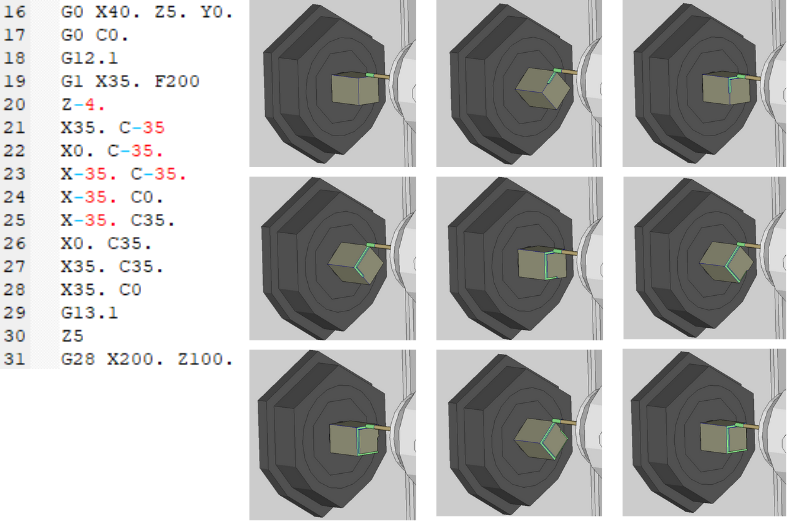
G12.1/G13.1/G121 COMMANDS:
The G12.1 command is used to switch to the polar coordinate system. When the G13.1 command is used, the G12.1 command becomes inactive. The G121 command is used instead of the G12.1 command. The codes for the part are written according to the coordinate system. In polar coordinates, the Y axis is assigned as the C axis, and while the part moves along the Y axis, it also moves proportionally along the C axis.
Example:
G17/G18/G19 COMMANDS:
These commands are used to select the active plane. The G17 command selects the XY machining plane. The G18 command selects the XZ machining plane. The G19 command selects the YZ machining plane.
The active plane must be correctly set for error-free circular, helical movements, diameter compensation movements, and hole cycles. Generally, in milling operations, the G17 (XY) plane is active, in turning operations, the G18 (XZ) plane is active, in hole operations in turning mode, the G17 (XY) plane is active, and in milling operations where the tool is in the X-axis direction, the G19 (YZ) plane is active.
G20/G21 COMMANDS:
*The G20 command sets the machine's length unit to inches. *The G21 command sets the machine's length unit to millimeters (mm).
G28/G30 COMMANDS:
*The G28 command enables the cutter to rapidly return to the machine's reference position. It is also referred to as the command to go to the machine reference (home) point. *The G30 command serves the same purpose as G28. The difference between them is that the G30 command directs the cutter to a different reference point instead of the machine reference (home) point established by G28.
The G28 and G30 commands can be used in G90 (absolute) and G91 (incremental) modes. Additionally, these commands can utilize the U, V, and W axes (incremental positioning axes) instead of the X, Y, and Z axes (absolute position axes).
Examples:
Example 1: G90 G28 X100. Y100. Z50. (The machine first moves to the specified X, Y, and Z positions in the line, and then goes to the machine position.)
Example 2: G28 U0. W0. (The machine goes to the machine position.)
Example 3: G91 G28 X100. Y100. Z50. (The machine moves from its current position by +100 on the X axis, +100 on the Y axis, and +50 on the Z axis. Then it goes to the machine position.)
Example 4: G90 G30 X200. Y100. Z100. (The machine first moves to the specified X, Y, and Z positions in the line, and then goes to the machine reference point specified for the G30 command.)
Example 5: G30 U0. W0. (The machine goes to the machine reference point specified for the G30 command.)
Example 6: G91 G30 X200. Y100. Z100. (The machine moves from its current position by +200 on the X axis, +100 on the Y axis, and +100 on the Z axis. Then it goes to the machine reference point specified for the G30 command.)
G41/G42/G40 COMMANDS:
*The G41 command offsets the tool to the left by the tool radius, depending on the direction of tool movement along the tool path. *The G42 command offsets the tool to the right by the tool radius, depending on the direction of tool movement along the tool path. *The G40 command cancels the G41 and G42 commands. In other words, it ensures that the center of the tool is on the tool path.
G43/G49 COMMANDS:
The G43 command allows you to add the length of the cutting tool to the reference point of the clamping (work spindle base point) on milling machines, enabling you to write code according to the tool tip. The G49 command is used to disable the effect of the G43 command.
Examples:
Example 1: G43 H5 (The length of cutting tool number 5 is added to the clamping reference point (work spindle base point)) G49 (Disables the effect of the G43 command)
Example 2: G43 Z0.1 H2 (The length of cutting tool number 2 is added to the work spindle base point, and the machine moves to point Z0.1) G49 (Disables the effect of the G43 command)
G43.4/G49 COMMANDS:
The G43.4 command enables the creation of NC programs based on the tool tip position during simultaneous operations on multi-axis milling machines. When this command is activated, movements relative to the workpiece can always be defined independently of the rotation of the rotary axes. Additionally, when this command is active, it keeps the tool tip position fixed relative to the workpiece even if the machine's rotary axes are rotating.
To activate the tool length offset used in this command, the tool number to be used must be written next to the G43.4 command with the H command. The G49 command disables the effect of the G43.4 command.
G1 G43.4 X__. Y__. Z__. H__ F__ (The G43.4 command is typically used in this template)
G43.4 H__. (Can also be used in this template)
Examples:
- G1 G43.4 Z1. H2. F600. (G43.4 activated) G49 (G43.4 command deactivated)
- G43.4 H1 (G43.4 activated) G49 (G43.4 command deactivated)
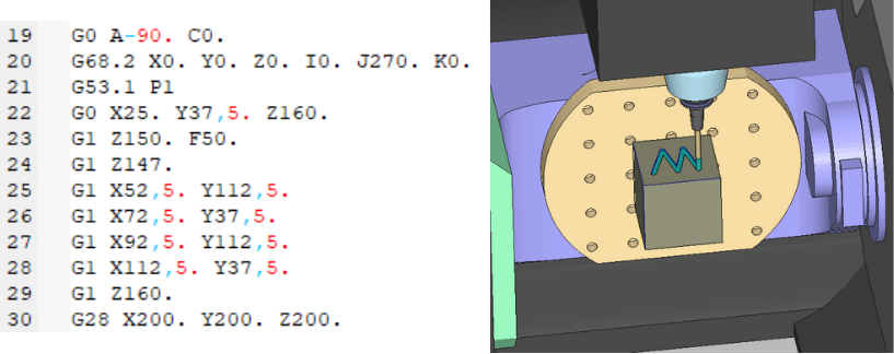
G68.2/53.1 COMMAND:
*The G68.2 command is used to define a tilted working plane on the workpiece in multi-axis milling machines. If machining is to be performed on any plane of the workpiece, the G68.2 command specifies the axis and the amount of rotation motion the machine head or table will make. The position of the point around which the workpiece will rotate (X,Y,Z) is entered. The direction and angle of rotation of the workpiece (I,J,K) are also entered. For example, the degree of rotation around the Z-axis is defined by the K parameter. The G69 command deactivates the G68.2 command.
G68.2 X__. Y__. Z__. I__. J__. K__. (The G68.2 command is typically used in this format)
G69
*The G53.1 command converts the plane to the angles provided by the G68.2 command in multi-axis machines. Therefore, before defining the G53.1 command, the plane rotation angles must be defined with the G68.2 command. Then, with the G53.1 command, the machine rotary axes are rotated according to the rotated angles in G68.2, and dynamic offset calculations are made based on the rotation angles of the rotary axes. That is, if the rotary axis is on the table, the G53.1 command calculates the position of the workpiece (e.g., G54) after the table rotation, or if the rotary axis is on the head, it considers the length of the rotary axis pivot after the head rotation and calculates the position of the tool.
Example:
COMMANDS BETWEEN G54 AND G59:
Commands between G54 and G59 are used to define the position of the workpiece on the CNC table. Names such as work offset number and work offset center are given.
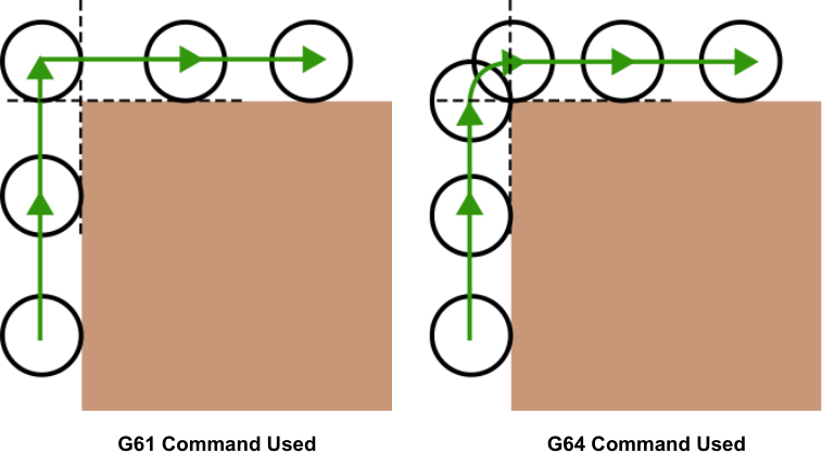
G61/G64 COMMANDS:
*The G61 and G64 commands adjust the feed rate of the cutting tool and keep the cutting position stable along the tool path.
When the G61 command is active, the machine moves to the sharp corner point until the end of the sharp linear axis rotation, and then starts moving on the other axis. In this case, traces may remain on the part at sharp corners.
*When the G64 command is active, it prevents the movement from stopping at sharp corners by creating a small radius, ensuring uninterrupted movement when sharp linear axis rotations occur.
Examples:
G65/M99 COMMAND:
The G65 command enables the calling of subprograms. The necessary subprogram number is written next to the P command, and then the subprogram is called.
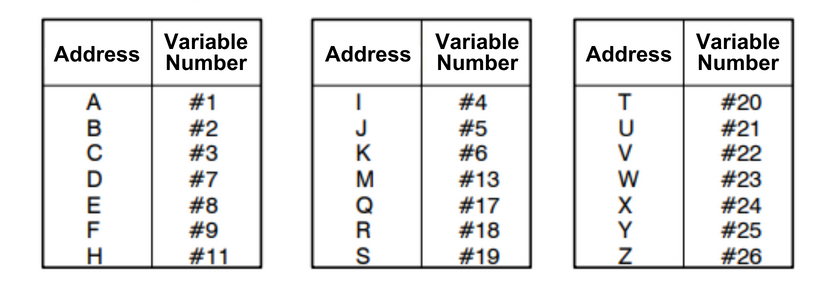
G65 P__. (The G65 command is generally used in this template) The letters defined next to the G65 command assign values to the specified variables in the subprogram.
M99 is the command that ends the called subprogram. When the M99 command is activated, the main program that calls the subprogram becomes active again. The main program continues to run from where it left off starting from the line where the subprogram was called with the G65 command.
Example:
Main Program: G65 P1234. A15 D26 (The macro program numbered 1234 is called, and within the subprogram #1 is assigned 15, and #7 is assigned 26) G90
Subprogram: O1234 G0 X#1 Y#7 (Moves to the position +15 on the X-axis and +26 on the Y-axis) M99
G81/G82 DRILLING CYCLE COMMANDS:
The G81 and G82 commands are used for hole drilling operations on milling machines. Within G81 and G82 commands, the tool's clearance distance (R) and feed rate (F) must be specified. The difference between them is that with the G82 command, the tool waits for the specified time (P) at the bottom of the hole, and if the drilling operation enters the repetition phase, the number of repetitions (K) must be indicated.
When the G98 command is used before these commands, the tool returns to the starting point after the operation. With the G99 command, the tool returns to the R distance.
G81 X__. Y__. Z__. R__. F__.
G82 X__. Y__. Z__. R__. P__. F__. K__.
Examples:
Example 1: G81 X40. Y60. Z-10. R2. F300. (Stops at a distance of 2mm from the surface of the part at the position of +40 on the X-axis and +60 on the Y-axis, and performs drilling operation at a depth of 10mm from the surface of the part with a feed rate of 300mm/min)
Example 2: G99 G82 X20. Y40. Z-20. R5. P2. F300. (Stops at a distance of 5mm from the surface of the part at the position of +20 on the X-axis and +40 on the Y-axis, and performs drilling operation at a depth of 20mm from the surface of the part with a feed rate of 300mm/min. It waits for 2 seconds at the bottom of the hole. The tool returns to the point indicated by R.)
G73/G83 PECK DRILLING CYCLE COMMANDS:
G73 and G83 commands enable drilling with pecking method on milling machines. In the G73 command, the retraction reference point is the tip of the drill bit. The G83 command specifies the retraction distance (R) from the surface of the part. With the G83 command, after drilling the hole, the tool stays at the bottom of the hole for the time specified (P). Peck depth (Q) and feed rate (F) must be included within the commands.
G73 X__. Y__. Z__. R__. Q__. F__.
G83 X__. Y__. Z__. R__. P__. Q__. F__.
Examples:
Example 1:
G73 X5. Y10. Z-40. R1. Q2. F200.
(The tool plunges in the -Z axis every 2mm until reaching a depth of 40mm from +5 in the X axis and +10 in the Y axis, taking a 1mm peck at each depth increment and retracting +Z axis by 1mm after each peck. It performs peck drilling at a feed rate of 200mm/min.)
Example 2:
G98
G83 X50. Y40. Z-70. R2. P1. Q3. F500.
(The tool plunges in the -Z axis every 3mm until reaching a depth of 70mm from +50 in the X axis and +40 in the Y axis, taking a 1mm peck at each depth increment and retracting +Z axis by 1mm after each peck. It performs peck drilling at a feed rate of 500mm/min. It pauses for 1 second when it reaches a depth of 70mm and returns to the initial position.)
G84 TAPPING CYCLE COMMAND:
The G84 command performs the tapping cycle operation. With this command, tapping is performed in the clockwise direction at the specified feed rate. Initially, the tapping feature is enabled with the M29 command and the spindle speed (S) is set. The tool is sent to the hole coordinates (X, Y axes). The thread depth (Z axis) and the safety distance where the tool will stop (R) are specified. The tool waits for the specified time at the bottom of the hole (P). The S/F ratio determines the thread pitch. The feed rate (F) is determined based on the calculations. If the tapping operation needs to be repeated, the number of repetitions (K) should be specified.
M29 S__.
G84 X__. Y__. Z__. R__. P__. F__. K__. (The G84 command is used in this template.)
Example:
G99
M29 S500.
G84 X50. Y40. Z-15. R5. P3. F250.
(The tool stops at a distance of 5mm from the surface of the part at the position of +50 on the X axis and +40 on the Y axis and performs the tapping operation at a depth of 15mm from the surface of the part at a feed rate of 250mm/min. The thread pitch is calculated as 2 from the S/F ratio. The tool waits for 3 seconds at the bottom of the hole. The tool returns to the R distance.)
G85 BORING CYCLE COMMAND:
The G85 command enables operations such as hole enlargement, slow hole drilling, and boring on milling machines. The command should include the tool's clearance distance (R) and feed rate (F). If the hole drilling operation enters a repetition state, the number of repetitions (K) should be specified.
G85 X__. Y__. Z__. R__. F__. K__. (The G85 command is used in this format.)
Example:
G99
G85 X20. Y30. Z-30. R10. F100.
(The tool halts at a distance of 10mm from the surface at the position of +20 on the X-axis and +30 on the Y-axis, and then drills a hole with a depth of 30mm from the surface at a feed rate of 100mm/min. The tool returns to the R distance.)
G90/G91 COMMANDS:
*The G90 command is defined as absolute programming. In other words, all motion points are defined relative to an active center, i.e., either the work offset center (G54, G55, etc.) or G53 (machine reference center). To move the cutting tool from its current position to a different point, simply write the coordinates of the destination point.
*The G91 command is defined as incremental programming. To move the cutting tool from its current position to a different point, the difference in distance between the two points must be specified.
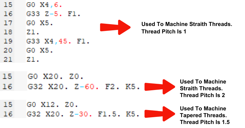
G33/G32 THREAD CUTTING CYCLE COMMANDS:
The G33/G32 commands are used for thread cutting on lathe machines. The G32 command is used for cutting straight and tapered threads, while the G33 command is used for cutting straight threads. The feed rate (F) must be specified within the commands.
G32 X__. Z__. F__.
G33 Z__. F__.
Examples:
G94/G95 COMMANDS:
*The G94 command defines the feed rate in millimeters per minute. *The G95 command defines the feed rate in inches per revolution.
G96/G97 COMMANDS:
*In the G96 command, the cutting speed is constant, while the spindle speed is variable.
*In the G97 command, the spindle speed is constant, while the cutting speed is variable.
The G97 command is used in milling operations, while in turning operations, either G96 or G97 is used.
G98/G99 COMMANDS:
*The G98 command allows the tool to retract to the safety distance (Z) at the end of a hole cycle on a milling machine.
*The G99 command enables the tool to return to the initial point at the end of a hole cycle on a milling machine.
NOTE: G98/G99 commands work similarly to G94/G95 commands on milling-turning machines.
M0/M1 COMMANDS:
*The M0 command allows the temporary pause of an active program.
*The M1 command enables the temporary pause of an active program if the optional stop switch is activated.
M2/M30 COMMANDS:
*The M2 command ends the program. Pressing the 'RESET' button is necessary to return to the beginning of the program.
*The M30 command ends the program and enables it to repeat itself.
M3/M4/M5 COMMANDS:
The M3 command rotates the spindle clockwise.
S__. M3 (The M3 command is used in this template)
The M4 command rotates the spindle counterclockwise.
S__. M4 (The M4 command is used in this template)
The M5 command stops the spindle.
Examples:
-S500. M3 (The spindle starts rotating clockwise at 500 revolutions per minute)
-S800. M4 (The spindle starts rotating counterclockwise at 800 revolutions per minute)
T/M6 COMMANDS:
T command is used for tool preparation or changing operations.
M6 command is used on machines equipped with a tool magazine to automatically call the tool from the magazine to the spindle.
On machines equipped with a tool magazine, the T command (without M6 code) is used alone as a tool preparation command. When M6 is entered on the following lines, the prepared tool is called to the spindle.
In machines without a magazine (such as turret lathes), the M6 command is not used. When the T command is activated, the turret rotates to bring the called tool to the active tool position.
Examples:
For machines with a magazine:
T5 M6 (Calls tool number 5 on the machine)
T6 (Prepares tool number 6)
For turret (magazineless) machines:
T0709 (Calls tool number 7 on the machine and activates offset number 9)
M8/M9 COMMANDS:
*M8 command activates the machine's coolant.
*M9 command deactivates the machine's coolant.
M98/M99 COMMANDS:
M98 command calls a subprogram. The number written after the P command specifies how many times the program will be repeated. The subprogram enabled by the M99 command ends, and the machine continues with the previous program.
M98 P__.
M99
Example:
M98 P56000. (Calls subprogram number 6000 to be repeated 5 times)
M99 (The subprogram ends, and the machine returns to the previous program)
Apr 2024 . MANUS

